In-fibre second-harmonic generation with embedded two-dimensional materials
Nature Photonics volume 16, pages769–776 (2022)Cite this article
Abstract
Silica-based optical fibres are a workhorse of nonlinear optics, providing ready access to a range of nonlinear phenomena including solitons and self-phase modulation. However, they have one fundamental limitation: due to the amorphous nature of silica, they do not exhibit second-order nonlinearity, except for negligible contributions from surfaces. Here we demonstrate second-harmonic generation in functionalized optical fibres by using a monolayer of highly nonlinear MoS2 directly grown on the fibre’s core. The MoS2-functionalized fibre exhibits a second-order susceptibility (χ(2)) value of 44 pm V–1 and a second-harmonic generation conversion efficiency of 0.2 × 10⁻³ m−2 W−1. This approach is scalable and can be generalized to other transition metal dichalcogenides and a wide range of waveguide systems. Our results demonstrate a new approach towards efficient in-fibre second-harmonic generation sources and may establish a platform for χ(2)-based nonlinear fibre optics, optoelectronics, photonics platforms, integrated optical architectures and active fibre networks.
Main
Optical fibres are one of the most studied and utilized platforms for nonlinear optics1. In particular, since the introduction of the photonic-crystal fibre2, they have found many exciting applications, such as supercontinuum white-light sources3,4,5, third-harmonic generation6,7 and several others8,9. Optical fibres stand out for their low loss, long interaction length and the ability to engineer their dispersive properties, which compensate for the small third-order susceptibility (χ(3)) nonlinear coefficient. However, the second-order parametric processes are expected to vanish in optical fibres since their fabrication typically relies on drawing amorphous materials10. Some second-order nonlinear responses can be induced, for instance, by electrical poling11 or by optical poling through irradiation with fundamental and second-harmonic (SH) light12,13 to break the inversion symmetry in optical fibres. The functionalization of optical fibres with materials with strong second-order nonlinearity and a large mode overlap, leading to a hybrid system with substantial second-order nonlinearities, would be a game changer and may enable fibre-based harmonic sources, optical parametric oscillators (OPOs), spontaneous parametric downconversion sources14 and fibre-based quantum communication.
Monolayer transition metal dichalcogenides (TMDs) are a well-studied class of two-dimensional (2D) semiconducting materials. Here we focus on monolayer MoS2 because of its strong second-order optical nonlinearity15,16. A first-principles analysis of the second-order nonlinear properties of monolayer TMDs predicts a comparable magnitude of second-order susceptibility (χ(2)) to other highly nonlinear semiconducting bulk crystals17. Although experimentally reported χ(2) values of MoS2 vary considerably15,16,17,18,19,20,21, they are all in the range of—or higher than—commonly used nonlinear bulk crystals. Moreover, second-harmonic generation (SHG) intensity is enhanced when the SH wavelength overlaps with the C-exciton band15 or A- and B-exciton band22,23 of 2D TMDs, all of which are in the visible spectral range and thus of immediate interest. For example, at resonance with the C exciton, the sheet susceptibility χ(2)MoS2,sheet of the MoS2 monolayer with a thickness of t = 0.65 nm is estimated to be approximately 8 × 10⁴ pm2 V–1 (ref. 15) corresponding to a bulk second-order susceptibility of MoS2: χ(2)MoS2,eff=χ(2)MoS2,sheett = 123 pm V–1 (ref. 20).
Most previous works in the integration of monolayer TMDs with fibres and waveguides relied on the mechanical transfer of TMDs onto nanostructures24 or waveguides25,26,27. In a similar approach, another study demonstrated chemical vapour deposition (CVD)-based two-step growth of TMD crystals in hollow-core and photonic-crystal fibres28. They showed guided-wave SHG in the hollow-core geometry. Nevertheless, hollow-core fibres must have a large modal cross-section to limit the propagation loss29. Moreover, the location of the functionalization layer coincides with the low-power area of guided waves. The combination of these two effects in hollow-core fibres leads to a small field overlap between the fundamental wave (FW) and TMD monolayer. The generated SHG also mostly contributes to radiation modes. In another way, one study demonstrated the thermal deposition of a few-layer MoS2 film within the optical-fibre cladding holes that are adjacent to the fibre core30. This periodically poled silica fibre exhibited SHG enhancement of 10% after the thermal poling process and functionalization with MoS2 film inside the 30-cm-long air holes. Nonetheless, the growth of the MoS2 film in the enclosed cladding holes makes it hard to access the crystals, for example, for further modification as periodic patterning of crystallographic structures.
In this work, we demonstrate a novel approach for functionalizing optical fibres to exhibit efficient SHG. We coat the surface of the exposed-core fibres (ECFs)31 with a highly nonlinear monolayer of TMDs32, similar to the process reported elsewhere33 using a scalable CVD-based process34. The minuscule thickness t leads to a small interaction length on planar substrates, curtailing the overall nonlinear conversion efficiency and hampering applications. Therefore, and in line with a previous report on enhanced third-harmonic generation and in-fibre photoluminescence (PL)33 in ECFs, the extension of the interaction length by integrating MoS2 in guided-wave systems will open new perspectives in nonlinear optics. The highly nonlinear MoS2 monolayers have functionalized SiO2-based optical fibres to establish a hybrid platform with a measured χ(2) value of 44 pm V–1 and an SHG conversion efficiency of 0.2 × 10⁻³ m−2 W−1. Moreover, an optimization of the overlap between the modal field and 2D materials has been investigated numerically but not experimentally.
Results
Figure 1a shows a schematic summarizing the fundamental concepts of this work. The integration of highly nonlinear TMDs into the ECFs is achieved with a scalable and reproducible CVD process34, where high-quality35 TMD monolayer crystals are directly grown on the ECF’s guiding core (radius, ~1 µm). Figure 1b shows a cross-sectional scanning electron microscopy (SEM) image of the ECF’s core, with additional images of the ECF displayed in Supplementary Fig. 1a,b. The CVD precursors are carried by the gas flow inside the reactor and grow on the exposed surface of the ECF’s core. The core is supported by three thin silica struts, with two air holes at the bottom and one open-air access hole on top of the functionalized surface. The crystal size and distribution are controlled by the precursor flow rate and position of the ECF in the reaction zone, and the results show densely distributed but randomly oriented monolayer crystals with an average size of 7 µm. Details on ECF fabrication are given in the Methods section. The small size of the guiding core leads to a comparatively large fraction of evanescent field that can interact with the overcoated layers and increases the field overlap of the TMD crystals with the fundamental and SH modes. The overlap of the monolayer location with the evanescent field of the guided mode provides a direct interaction of guided light and TMD crystals. Possible further optimization of this overlap by means of a thin dielectric overcoat is discussed in the Supplementary Information but not experimentally explored. The fibre is, hence, nonlinearly functionalized and the optical properties of the TMD crystals can be used in a guided-wave geometry.
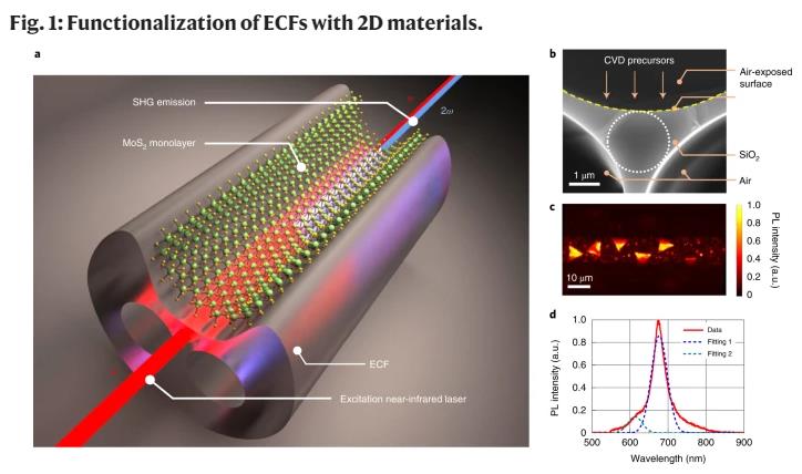
a, Illustration of the concept to demonstrate SHG with embedded 2D materials on an ECF. ω, Fundamental frequency; 2ω, Second harmonic. b, Cross-sectional SEM image of the core region of the ECF. The dotted circle denotes the effective core area of the ECF. The exposed surface is highlighted by a dashed yellow curve. c, Top-view PL mapping of a section of MoS2-coated ECF. d, PL emission spectrum from a typical monolayer of MoS2 in c under the excitation of a 532 nm laser after filtering by long-pass filters at 550 nm.
Fibre characterization
The outstanding advantage of waveguides functionalized with 2D materials is that the linear properties including dispersion and guided modes remain virtually unchanged, except for higher losses due to the absorption of 2D crystals (Supplementary Fig. 9a shows the calculations). The nonlinear interaction in these waveguides is solely due to the action of the MoS2 monolayer at the interface33.
In the first step, we used the previously established method33 to characterize the location, quality and distribution of MoS2 on the fibre and its interaction with the core mode. By performing atomic force microscopy imaging, we found a thickness of 0.9 nm (Supplementary Fig. 2a,b). The Raman spectrum of the MoS2 crystals displays a characteristic spacing of 20.5 cm−1 between two modes, which confirms the successful deposition of monolayers of TMD crystals on the ECF’s core region. We further carried out PL mapping along the ECF core (Fig. 1c). This measurement was performed by a confocal PL-lifetime microscope (PicoQuant MicroTime 200). Typical MoS2 crystals with a size of roughly 7 µm can be seen in this image. Figure 1d exhibits the PL spectrum of a typical crystal shown in Fig. 1c. Spectroscopic analysis was used to unravel the relative contributions of the A- and B-exciton species observed in MoS2. As shown in Fig. 1d, the PL emission reveals the exciton peaks at 677 nm (dotted blue line) and 613 nm (dotted cyan line) with a spectral full-width at half-maximum of 45 nm for both cases. These values are comparable to those of high-quality crystals grown on planar substrates by the same technique34.
Because direct interaction between the guided modes and monolayer crystals is crucial for efficient nonlinear interaction, we investigated the coupling of TMDs to the core mode of the ECF. Figure 2 shows a schematic of the experimental setup used. The excitation light source was a 532 nm laser (Lighthouse Photonics Sprout) focused on the fibre core by a ×40 microscope objective. The incident power was varied using a combination of a half-wave plate (HWP) and a polarizer. To obtain systematic statistics of the crystal ensemble on the fibre core throughout the fibre length, we imaged the PL emission perpendicular to the ECF using a microscope objective, a camera and a pair of 550 nm long-pass filters. Scanning the setup along the length of the fibre allowed us to obtain a series of images, which were stacked to record the length-wise distribution of PL-active monolayer crystals. Such a stack is depicted in Supplementary Fig. 5b. By tweaking the fabrication process, we obtained a MoS2 monolayer coverage of up to 43.4%, as opposed to 5.4% in previously reported results33.
Fig. 2: Schematic of the experimental setup for PL and SHG measurements.
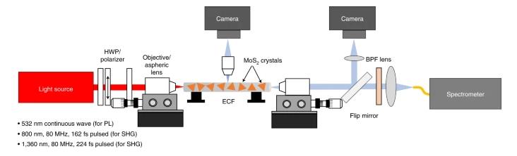
HWP, half-wave plate; ECF, exposed-core fibre; BPF, band-pass filter.
SHG from ensembles of crystals
The SHG is governed by the interplay of second-order susceptibility, mode matching and phase matching within the 7-µm-long flakes. Because SHG is an intrinsic property of TMDs, it also serves to quantify the material quality and layer thickness. Nonlinear experiments were carried out with a pulsed Ti:sapphire laser (Coherent, 80 MHz repetition rate, 162 fs pulse width; Supplementary Fig. 4), the output of which was coupled into the fibre core using an aspheric lens with a focal length of 3.1 mm. Light leaving the fibre was collimated with a ×40 objective and coupled into a spectrometer (Horiba Jobin Yvon Triax) with a cooled Si charge-coupled device (CCD) detector to measure the SH spectra after passing through a series of band-pass filters. The power was controlled by an HWP and linear polarizer, as illustrated in the schematic of the experimental setup. The input polarization was adjusted by a second HWP in front of the aspheric lens.